Lecture from: 25.11.2024 | Video: Videos ETHZ
Overview
Let’s recap our journey through abstract algebra so far.
We began with monoids, which are algebraic structures with an associative binary operation and an identity element. Then we explored groups, a special type of monoid where every element has an inverse. Building upon groups, we defined rings, which have two operations, addition (forming an abelian group) and multiplication (forming a monoid), connected by the distributive property.
From rings, we explored two main paths:
-
Gaussian Integers Modulo a Gaussian Prime: We touched upon the idea of taking Gaussian integers modulo an irreducible Gaussian prime (like ), creating a finite field. This is analogous to constructing from by modding out a prime . However, we didn’t delve deeply into the details of this construction.
-
Fields and Polynomial Rings: The other path focused on fields, which are commutative rings where every non-zero element has a multiplicative inverse. We then explored polynomial rings over a field . This allowed us to construct Galois fields (finite fields) by taking the quotient ring , where is an irreducible polynomial. We saw that .

Within polynomial rings, we also briefly discussed polynomial interpolation. A key fact is that a non-zero polynomial of degree at most can have at most roots in a field.
Today’s lecture will explore the intersection of these two paths, addressing the question: Given two different polynomials of degree at most , how many common roots can they have? Or can they have no common roots at all?
Example: Finding Inverses in
Consider the field , which is the ring of polynomials with real coefficients modulo the irreducible polynomial .
-
Irreducibility: is irreducible in because its discriminant () is negative, meaning it has no real roots. The Fundamental Theorem of Algebra tells us that a polynomial over the reals is irreducible if and only if it is linear or a quadratic with a negative discriminant. Since there are no linear factors that divide , where , is irreducible. Thus all non-zero elements have inverses.
-
Finding the Inverse of : Let’s find the multiplicative inverse of in . We are looking for a polynomial such that .
-
Setting up the Equation: This congruence translates to the equation for some polynomial . Since we’re working modulo , the degree of the product can be reduced to less than 2 using the relation .
Expanding the left side gives . Substituting , we get .
Thus we have:
-
Equating Coefficients: Comparing coefficients of the powers of on both sides, we get the following system of equations:
- (coefficient of )
- (constant term)
-
Solving the System: We can solve this system using various methods (substitution, elimination, matrix inversion). Using matrix notation, we have:
The inverse of the matrix is .
Multiplying both sides by the inverse matrix gives:
So, and .
-
The Inverse: Therefore, the multiplicative inverse of in is .
Example:
Let’s illustrate finding inverses in the field , constructed by taking the polynomial ring modulo the irreducible polynomial .
Suppose we want to find the inverse of . We seek a polynomial , where , such that .
While we won’t solve this completely here, the setup would involve expanding the product, reducing modulo (using the fact that ), and equating coefficients to form a system of equations in , , and . This system can then be solved to find the inverse. This process is analogous to the previous example with .
Powers and Generators in Finite Fields
Now, let’s explore powers and generators within the same field, .
-
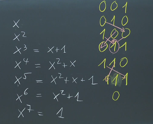
Powers of : Consider the powers of : . Since is a field of polynomials, when we have , we must reduce this using our modulo .
-
Reduction Modulo :
- and are already in reduced form (degree less than 3).
-
Multiplicative Group: The non-zero elements of form a multiplicative group. The number of these non-zero elements is . Here’s the complete list in their standard reduced form: .
-
Lagrange’s Theorem and Generators: Lagrange’s theorem states that the order of any element in a finite group must divide the order of the group. In our case, the multiplicative group has order 7, which is prime. This means every element except the identity (1) has order 7. This has a powerful consequence.
Generators of the Multiplicative Group
An element is a generator of a group if its powers generate all the elements of the group. In our case, Since every element (except 1) has order 7, which is equal to the order of the multiplicative group, every non-identity element in the multiplicative group of is a generator. In the example we saw that generate all 7 elements. Thus we have generators. happens to be one of these generators.
Not part of the actual exam stuff, interesting regardless…
Linear Feedback Shift Registers (LFSRs) and Their Properties
Linear Feedback Shift Registers (LFSRs) provide a way to generate sequences of elements in a finite field, particularly . They are simple hardware circuits with fascinating mathematical properties.
1. Construction and Operation:
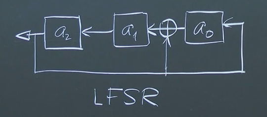
An LFSR is defined by a polynomial over , such as . The degree of the polynomial determines the length of the LFSR (in this case, length 3). The non-zero coefficients (excluding the leading coefficient) specify the “taps” for feedback.
The LFSR operates by shifting its contents (bits) to the left. The new leftmost bit is calculated as the XOR sum of the bits at the tap positions. In our example, we XOR the values at the and taps (last two values). This feedback mechanism creates a recurring sequence of states.
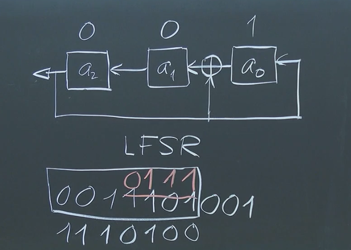
In the provided example with the initial state representing the polynomial , the LFSR evolves as follows, with each state corresponding to a power of modulo :
- :
- :
- : ()
- :
- :
- :
- : (, which also corresponds to )
- : back to initial state
The LFSR cycles through non-zero states before returning to the initial state.
More info here: Wikipedia: LFSR
2. Statistical Properties:
For an LFSR of length with a “primitive polynomial” (a polynomial that generates the entire multiplicative group of the field):
- Period: The LFSR cycles through distinct non-zero states. The all-zero state is excluded as it does not change during the shift operation.
- Balance: Over one period, there will be ones and zeros. The sequence is almost perfectly balanced between 0s and 1s.
3. Applications and Limitations:
- Pseudorandom Number Generation (PRNG): In the past, LFSRs were considered for PRNGs. However, they are now deemed cryptographically insecure. Observing a sufficiently long segment of the sequence allows one to reconstruct the feedback taps and predict the entire sequence using linear algebra.
- Distance Measurement: LFSR sequences have been used for distance measurement, for example, in radar systems and interplanetary ranging. A modulated signal based on an LFSR sequence is transmitted. The time delay in the received (and weakened) signal corresponds to the signal’s travel time. By correlating the received sequence with shifted versions of the original sequence, we can determine the time delay and thus calculate the distance. This technique is very related to the autocorrelation method discussed in the next point.
- Spread Spectrum Communication: LFSR sequences are used in spread spectrum communication. The transmitted signal is spread across a wide frequency band, making it resistant to jamming and interference. This resistance comes from a key property of LFSR sequences related to autocorrelation.
4. Autocorrelation and Spread Spectrum:
The autocorrelation function of a sequence measures the similarity between a sequence and shifted versions of itself. For an LFSR sequence with a primitive polynomial, the autocorrelation function is almost flat, except for a large peak at zero shift (where the sequence perfectly overlaps with itself). The Fourier transform of the autocorrelation function (the power spectral density) is also relatively flat, indicating the signal’s energy is spread across a wide range of frequencies. This flat spectrum is precisely why LFSR sequences are useful in spread spectrum communication. A narrowband jammer would only affect a small portion of the spread spectrum signal, leaving most of the signal intact.
5. Example of Correlation in Distance Measurement:
Let’s consider a simple example with the sequence 001 generated by , giving us the periodic sequence 0011101. Suppose we transmit a signal based on this sequence and receive a shifted version like 1110100. By comparing the received sequence with all possible shifts of the original sequence, we find the greatest correlation when the received sequence is shifted three positions to the right. This shift corresponds to the time delay, which is related to the distance of the round trip of the transmission.
Properties of Finite Fields
Finite fields, also known as Galois fields, possess some remarkable properties:
-
Existence and Uniqueness: For every prime and positive integer , there exists a unique (up to isomorphism) finite field with elements, denoted . This means any two finite fields with the same number of elements are essentially the same, just with potentially different representations of their elements.
Construction of Finite Fields
Recall: Finite fields are constructed as quotient rings of polynomial rings. is constructed as , where is an irreducible polynomial of degree over . itself is isomorphic to .
-
No Other Finite Fields: There are no other finite fields besides those of the form . Every finite field must have a prime power number of elements.
-
Cyclic Multiplicative Group: The multiplicative group of any finite field (where ) is cyclic. This means there exists an element , called a generator or primitive element, such that every non-zero element of the field can be expressed as a power of .
Error Correcting Codes
Error correcting codes are crucial for ensuring data integrity in digital communication and storage systems. They protect against data corruption caused by noise, interference, and other sources of error.
The Need for Error Correction: Storage media and communication channels are inherently imperfect. Bits can be flipped or corrupted during transmission or storage, leading to data loss or misinterpretation. Error correcting codes add redundancy to the data, enabling the detection and correction of these errors.

Repetition Codes: A Simple Approach
A basic error correcting code is the repetition code. The idea is simple: repeat each bit multiple times to create redundancy.
- Encoding: A 3-bit repetition code encodes 0 as 000 and 1 as 111.
- Decoding (Majority Voting): The received sequence is decoded by majority voting. For example, 101 is decoded as 1.
Effectiveness and the Binary Symmetric Channel:
The binary symmetric channel (BSC) is a simple model for a noisy communication channel.
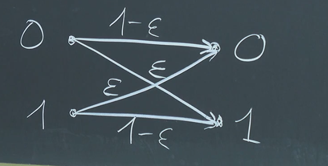
- : Probability of a bit flip (error).
- : Probability of correct transmission.
Error Probability Calculation
- Without error correction: .
- With 3-bit repetition code: for small .
- With 5-bit repetition code: for small .
Increasing redundancy (more repetitions) improves error correction but at the cost of increased bandwidth or storage.
Hamming Codes: A More Sophisticated Approach
Hamming codes offer a more efficient way to achieve error correction. They rely on the concept of Hamming distance.
Hamming Distance
The Hamming distance between two bitstrings of equal length is the number of positions at which the corresponding bits differ.
Encoding for Larger Hamming Distance: The core principle is to encode messages into codewords such that the minimum Hamming distance () between any two codewords is maximized. A larger allows for the correction of more errors.
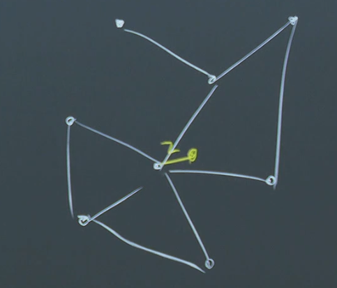
Error Correction Capability
A code with can correct up to errors.
Decoding and Error Correction: Decoding involves finding the closest valid codeword (in terms of Hamming distance) to the received word.
Constructing Hamming Codes: Hamming codes use parity bits (linear combinations of message bits) to achieve a larger Hamming distance.
(7, 4) Hamming Code
A (7, 4) Hamming code encodes 4 message bits into 7-bit codewords. The encoding can be represented by a matrix multiplication:
Decoding involves checking parity bits. Failed parity checks indicate errors, and the pattern of failures pinpoints the error location.
Formalizing Encoding and Decoding
- Encoding Function: maps a -bit message to an -bit codeword.
- Decoding Function: maps an -bit received word to a -bit message.
The decoding function should recover the original message if the number of errors is within the code’s correction capability: If , then , where is the received word, is the original message, and is the error correction capability.
Reed-Solomon Codes and Finite Fields
You might need to skip to the final few chapters…
Reed-Solomon codes, a powerful class of error-correcting codes, utilize finite fields and polynomial evaluation.
Reed-Solomon Encoding
Encoding in a Reed-Solomon code over a finite field involves:
- Message as a Polynomial: Represent the message as a polynomial with coefficients in .
- Evaluating the Polynomial: Choose distinct elements from . The codeword is then . Note that . This is because there are at most distinct elements in .
Minimum Distance of Reed-Solomon Codes
A Reed-Solomon code with parameters has a minimum distance .
Proof
1. Core Idea: Polynomials and Roots
A non-zero polynomial of degree can have at most roots in any field.
2. Reed-Solomon Codewords as Polynomial Evaluations
Recall how Reed-Solomon codes work:
- Message Polynomial: A message is represented as a polynomial of degree at most .
- Codeword: The codeword is obtained by evaluating at distinct points in the finite field : .
3. Considering the Difference of Two Polynomials
Now, let’s consider two different messages, and , both of degree at most . Their corresponding codewords are and . We want to find the minimum Hamming distance between and , which is the number of positions where they differ.
Let . This is also a polynomial of degree at most . The codewords and will agree at a position if and only if , which is equivalent to . In other words, codewords agree exactly when . This means has a root at .
4. Connecting to Hamming Distance
The Hamming distance between and is the number of positions where they differ, which is minus the number of positions where they agree. Since and agreeing means that the difference of the polynomials is 0, we are searching for the number of places isn’t zero. From step one we know that any polynomial of degree has a maximal distinct roots. The number of places is zero is at most . Thus, the minimal number of spots they disagree must be at least . Since we selected distinct points , which is spots to evaluate, then we can subtract at most zeros from the number of distinct positions. This gives a .
Example
Let’s consider a simple example over with and . This means our message polynomials will have degree at most .
- Evaluation Points: Let’s choose , , , and .
- Message 1: . The codeword is .
- Message 2: . The codeword is .
- Difference Polynomial: .
- Roots of d(x): has one root in , namely . This corresponds to the second position where the codewords agree ().
- Hamming Distance: The Hamming distance between and is 3 (they differ in the first, third, and fourth positions). This is consistent with .
This example demonstrates how the number of agreement points between two codewords relates to the roots of the difference polynomial and ultimately determines the minimum distance of the Reed-Solomon code.
Practical Application of Reed-Solomon Codes
Reed-Solomon codes are highly effective for correcting burst errors, making them suitable for applications like CDs, DVDs, barcodes, and data transmission.
Let’s consider a practical example:
1. (256, 224) Reed-Solomon Code:
A (256, 224) Reed-Solomon code encodes 224 information symbols into 256 codeword symbols. Typically, symbols are bytes (8 bits), so this code takes 224 bytes of data and adds 32 bytes of redundancy.
- Finite Field: In practice, is often used. This field allows for representing each symbol as a byte. We could theoretically choose an as maximal . However we only require thus suffices and each coefficient is a byte, with and . This leads to a , meaning we can correct up to errors.
2. Interleaving for Burst Error Correction:
On CDs, errors often occur in bursts due to scratches. A single scratch could corrupt multiple consecutive bytes, rendering straightforward Reed-Solomon decoding ineffective. To address this, interleaving is used.
- Spreading the Data: The data is spread out across the CD in a specific pattern before encoding. This ensures that a localized burst error affects multiple codewords rather than a long continuous segment within a single codeword. Each codeword now contains bytes which are seperated on the CD by positions where is large enough so that no scratch can scratch of our bits. If we had a burst error within symbols of consecutive symbols then we could also decode this using the same principle.
3. Example: Double Interleaving on CDs:
CDs often employ double interleaving:
- Inner Code: A (28, 24) Reed-Solomon code is used. Thus . . This means we can correct two errors with this interleaving strategy.
- Outer Code: Another (32, 28) Reed-Solomon code is applied to the output of the inner code. Thus , . Again we can correct two errors with this interleaving strategy.
This double interleaving scheme enhances the ability to correct burst errors, ensuring data integrity even in the presence of scratches or other localized damage. This illustrates how theoretical concepts from coding theory, like Reed-Solomon codes and Hamming distance, are combined with practical techniques like interleaving to create robust and reliable data storage and transmission systems.
Continue here: 21 Logic, Proof Systems, Logical Consequence, Syntactic Derivation
